Reach adjust headsets allow cyclists to fine-tune their bike’s reach, extending or reducing reach by a few millimeters.
Here’s how a reach adjust headset works along with a detailed look at the installation procedure.
Contents
A key element of achieving maximum comfort on a bicycle is in the reach. The best riding position is one where a cyclist is not extended too far forward nor pushed too far back. Setting the reach is thus a key element of fitting a bike to a rider.
The way to achieve close to the perfect reach adjustment is by means of the stem. For some cyclists, particularly professional racers, the top tube can figure into the calculation. But all things equal on a mass-produced frame, altering stem length is the easiest way to immediately change the reach.
However, stems are available in lengths from 35mm up to 160mm in 10mm increments. The most common lengths are from 80mm to 120mm. A cyclist wanting to dial in stem length is restricted to 10mm—or they can install a reach adjust headset.
A reach adjust headset allows a much finer incremental gradation. In the case of the reach adjust headset the subject of our attention here, ±5mm, the adjustment measured from the center of the steerer to the limit of the headtube’s inner diameter would increase or decrease by 5mm, or a total 10mm distance between front to rear (if simultaneously set to the rear and the front). 5mm is a seemingly minute distance, but can make all the difference for a many cyclists.
Reach Adjust Headset Components
We’ll demonstrate the install on a carbon eMTB frame.
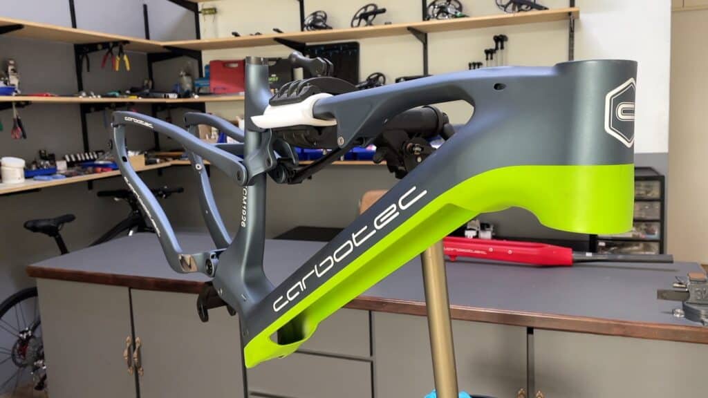
A road bike frame would have been more appropriate, but as strictly a components company, we found that getting hold of a modern frame with exactly the right spec is almost impossible.
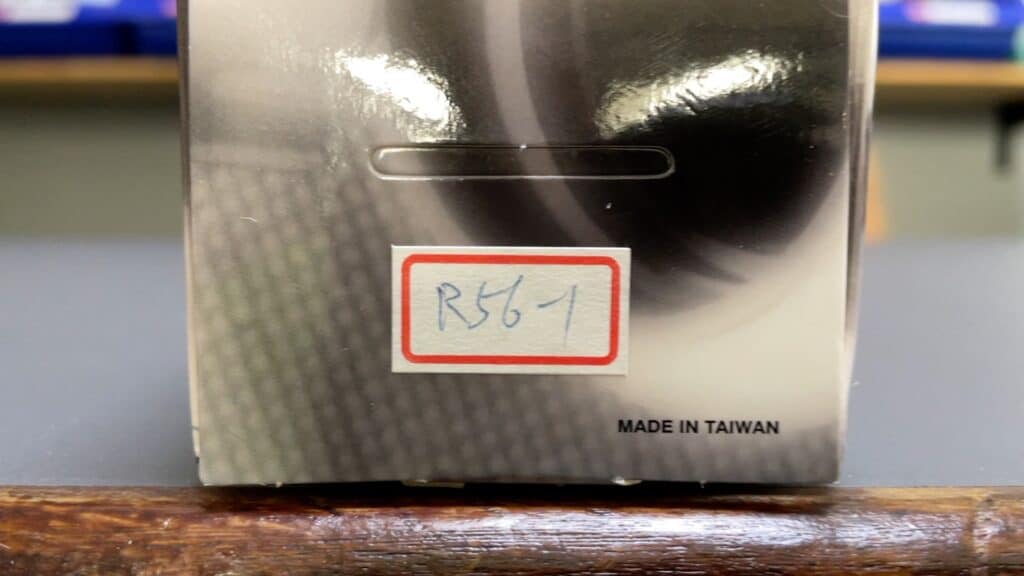
For reference sake, the model in our catalogue is as indicated in the image.
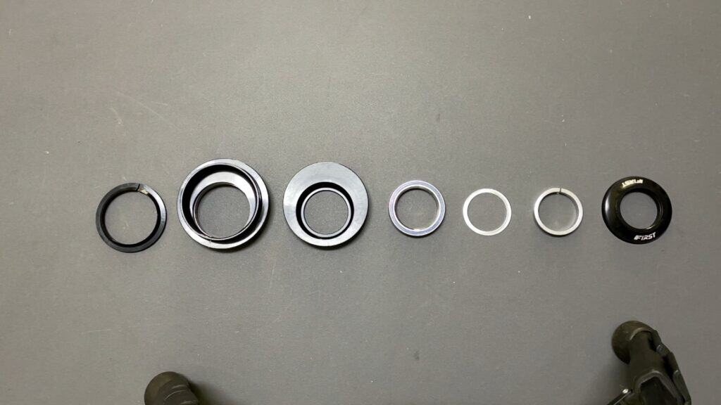
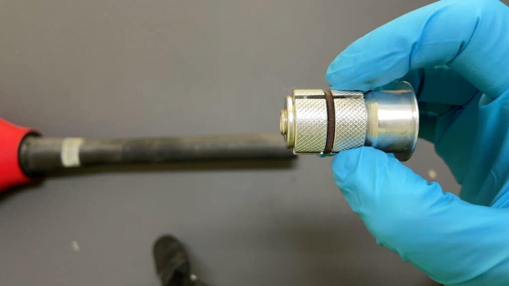
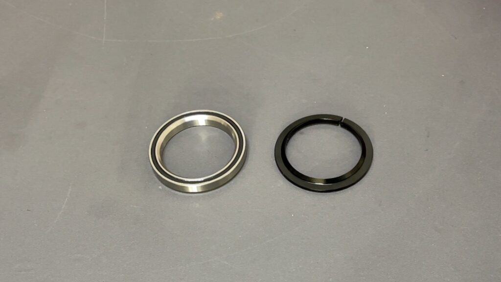
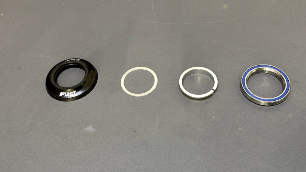
The components are the usual pieces that go into a standard integrated headset.
From left to right you have the crown race and its bearing cup right beside it which contains the lower sealed bearing. Note the offset design where one edge is thicker than the other.
The same applies to the top cup just to the left. Then you have the bearing, spacer/washer, compression ring, and dust cap.
As with all headsets, this one comes with a star nut by default, which of course, is no good if you have a carbon frame because you’ll also have a carbon fork and for that you need a spacer, not an expander.
The Cups—Eccentric / Offset
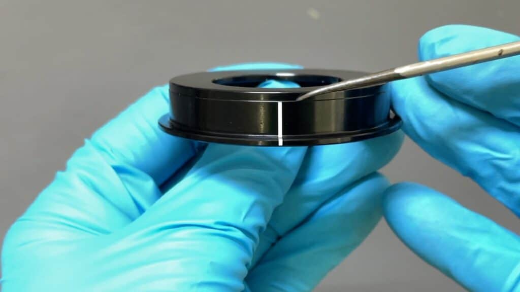
The key to a reach adjust headset is in the cups.
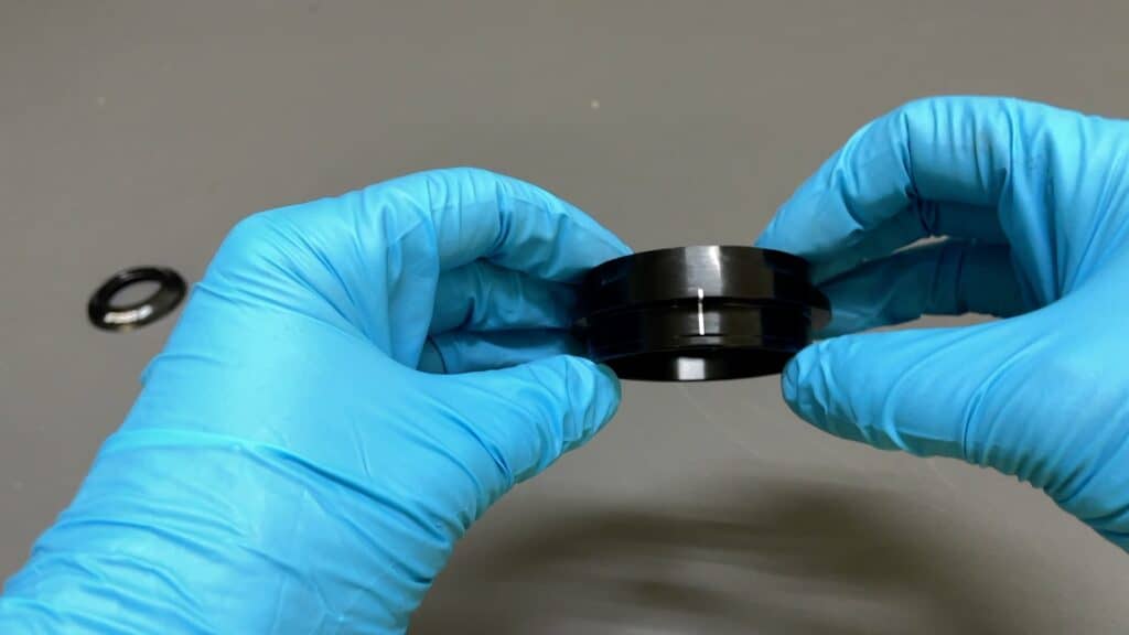
You need to make sure that either a +5mm (forward facing) or -5mm (rear facing) installation is aligned exactly with the center of the headtube. Exact alignment ensures the steerer is not tilted to the left or right which will mean the fork is off-center which in turn may affect the steering.
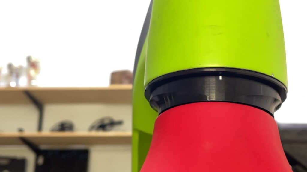
The while line marks the center of the head tube. The center of the head tube is indicated by the bike brand’s logo which is invariably placed exactly on the imaginary central axis line by the personnel who apply a bike’s decals. (They do it by sight and are uncannily accurate in placement).
The offset effect is achieved by machining the internal diameter (ID) flush against the edge of the cup which is, discounting the thickness of the cup itself, the head tube’s ID.
The Lower Cup
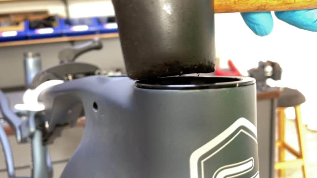
The trick to fitting the lower cup is to align the white line with the center of the head tube, wedge it in slightly, then tap it home with a rubber mallet.
It’s easiest on a work stand that can be reversed so that gravity works for you—hammer the cup home with even taps right the way around the circumference.
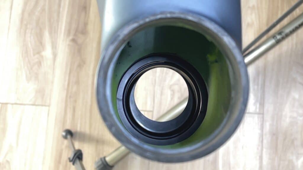
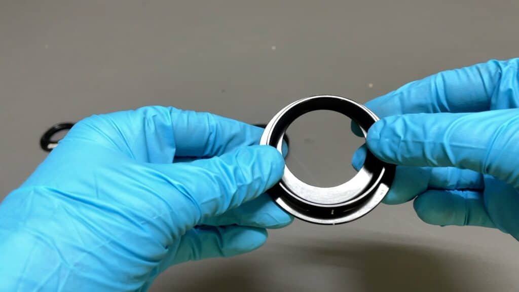
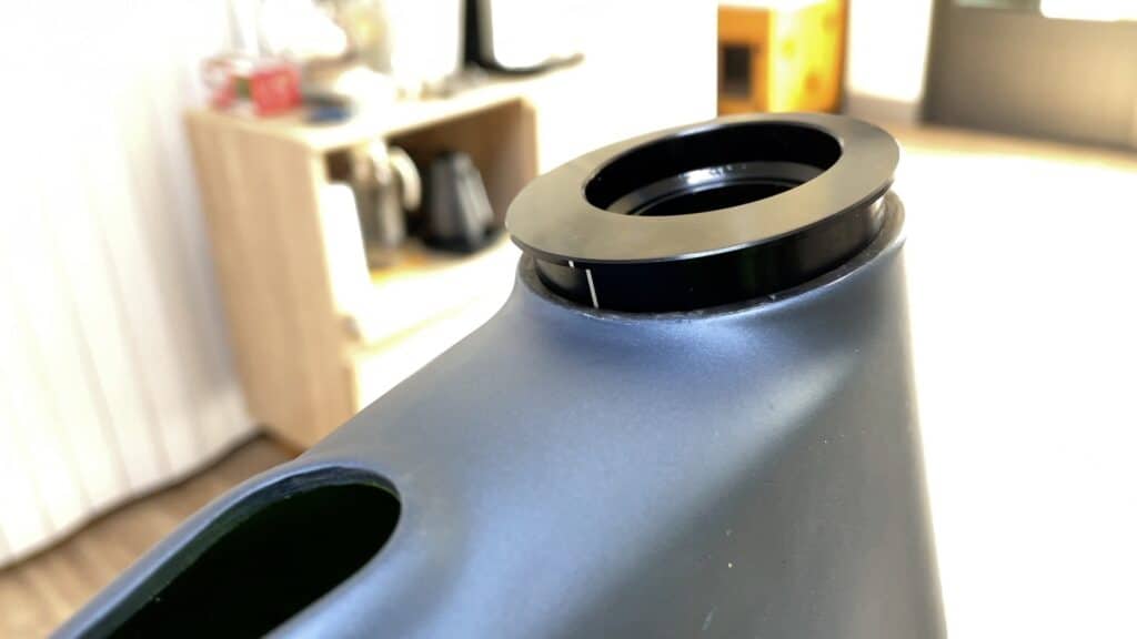
Looking from above at the installed bottom cup. You’ll note the reach is set to -5mm since the offset is flush with the rear ID.
Of course, the reach cannot be adjusted on the fly: you have to decide whether your bike’s reach is to be adjusted by +5 or -5 and then install accordingly. Changing the reach requires removing the fork, removing the cups, reversing them, then reassembling the lot.
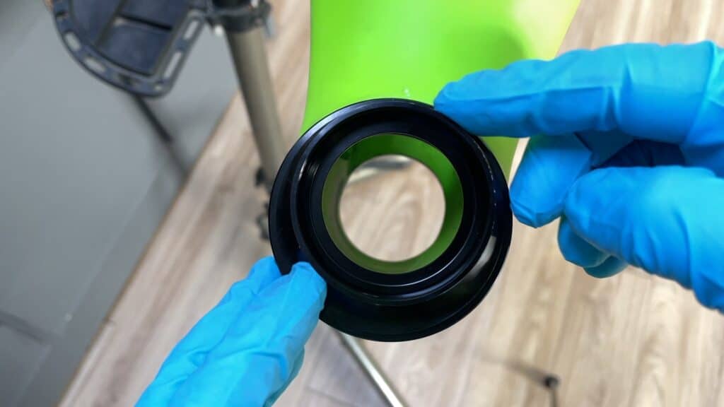
This the view of the bottom cup from the install position, that is, upside down. The “thicker” frontal area indicates the offset is positioned at the rear, a -5mm reach.
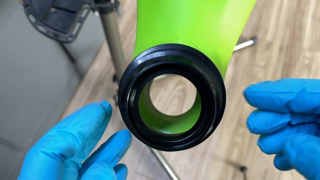
The opposite view with the cup rotated through 180 degrees into the +5mm reach position.
We machined the OD (outer diameter) of this particular cup a fraction more than the official spec so it would rotate easily in the head tube for demo purposes.
The Upper Cup
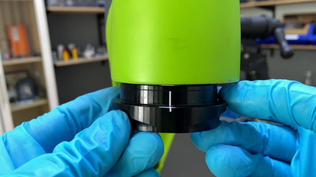
This cup is offset to the same degree as the lower cup and you use the white line to align the cup in the head tube in the same way as the lower cup.
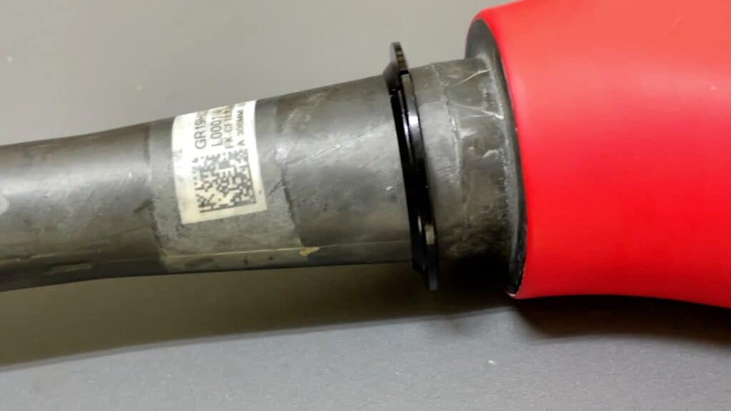
To help square the cup in the head tube making installation easier, we’ve machined a 1mm groove along the edge.
Without this groove, the cup would sit directly on top of the head tube making installation more difficult.
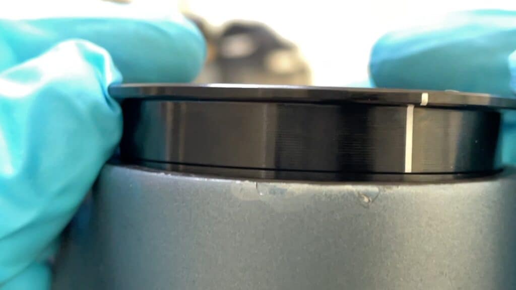
Here the cup is almost inserted to the width of the groove.
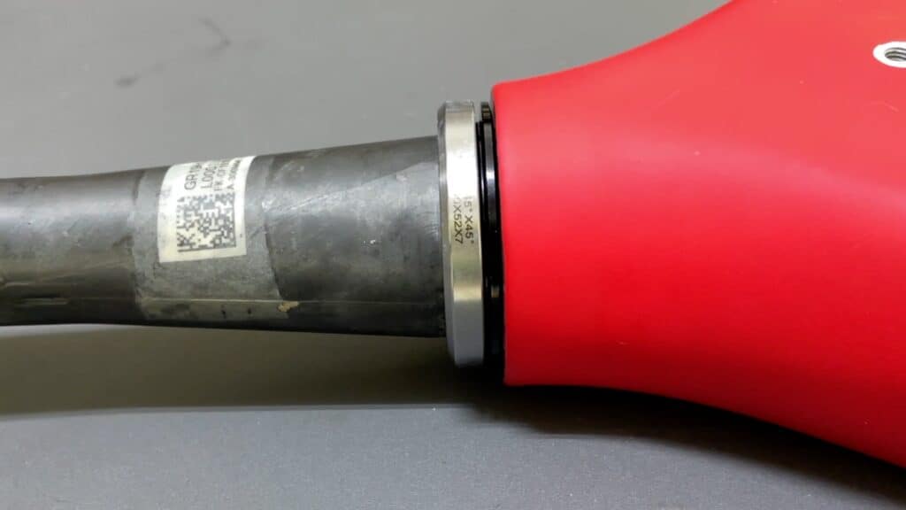
You push the cup down the full width of the groove into the head tube. Then you are ready to tap it all the way in with a mallet. Without the groove you would have to somehow steady the cup as you tap it home resulting a more lopsided start to the install. Having already installed slightly into the head tube, the cup moves much more easily into the head tube.
The view from the rear.
Using a hard rubber mallet on an anodized alloy cup won’t damage or mark the surface. Using a cloth between the mallet and the cup to absorb the impacts also works if you are concerned about scratches—well used mallets may contain small particles of embedded metal or other materials depending the age and use cases for that particular mallet.
Installing The Fork
Standard fork installation procedures apply. The main issue with a reach adjust headset is making sure the cups are aligned exactly in the center of the head tube, top and bottom. If not, what effectively amounts to a slight alteration of the geometry
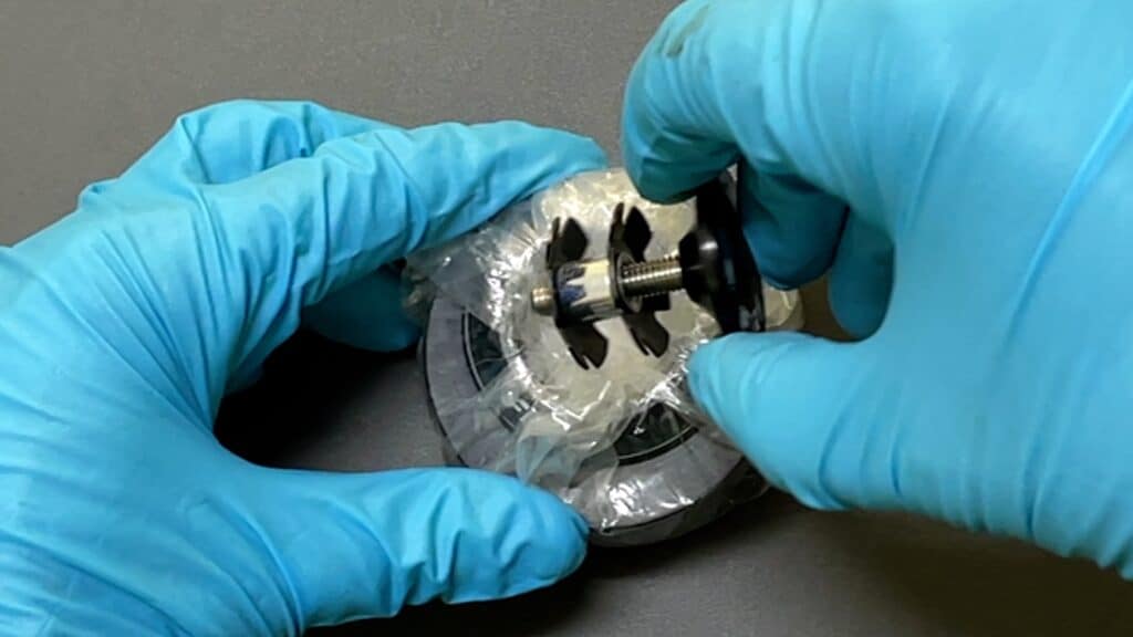
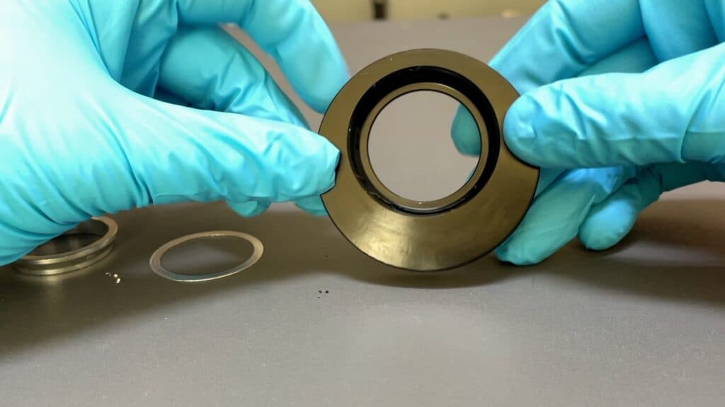
The crown race and accompanying bearing are the first to go on.
The crown race’s split allows it to expand over and onto the fork crown where it sits securely under its own tension.
The sealed bearing is designed to slot in on top.
By preparing the fork in this way, the assemblage slides up and into to the head tube in one motion.
Holding the fork in place with one hand, you can slide the final components onto the steerer to so it will hold itself in place.
From right to left, the install is bearing, compression ring, spacer, and dust cap. We don’t show the complete process—involving measuring then marking the steerer, cutting it to size, then finishing off with the spacer and compression bolt install—since this frameset is used for a variety of R&D purposes.
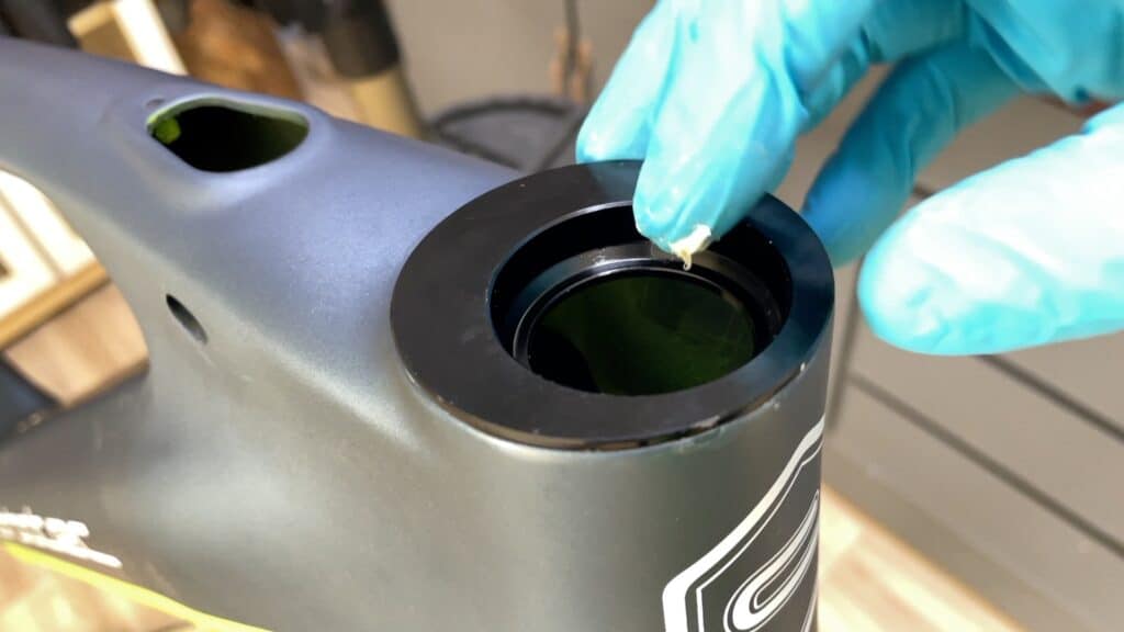
A light smear of grease on the cup and the sealed bearing reduces the chance of noise from any small degree of movement when the bike is in motion.
Pushing the compression ring down against the bearing centers the steerer in the assembly.
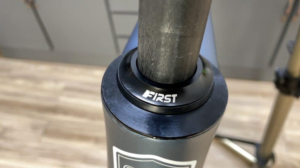
The dust cap is designed to grip the steerer tightly, which secures the setup, freeing your hands to complete the final steps of a working installation.
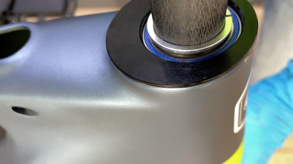
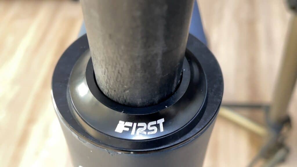
Note the position of the headset in terms of reach adjust to the rear of the head tube which is the -5mm position.
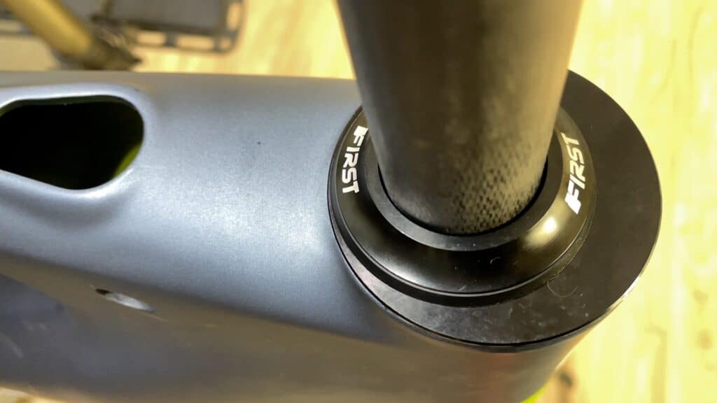
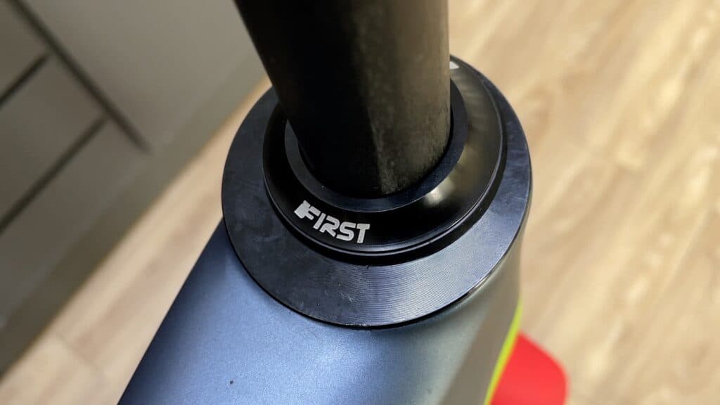
In contrast, the +5mm position, with the steerer secured at the furthest adjustable extent.
Video